In my earlier post at: waynemerry.wordpress.com/2012/07/25/improving-the-backpackable-vertical-antenna/ I still had two pending jobs:
- Fix the crocodile clip on the tapped loading coil
- Build an ugly balun
Crocodile clip
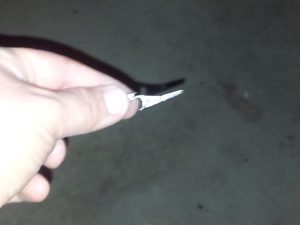
Clearly they don’t make ’em like they used to. I had not used this clip for very long, but already there were signs of stress, shown below:
The top part of the clip is bending and cannot take any force without further yielding. The material is “stooffed”.
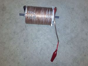
A simple job, and also I can fix a problem with the tapping coil being a little too short. I recently purchased some LiPo chargers that came with crocodile clips for their DC power, but I use alternative cables with anderson poles – no clips for my DC power thank you!
The job nearly finished is shown below, with just some electrical tape over the solder joint. Much easier to connect to the bottom of the coil for bypassing, which I need to do on 20 and above. Bonus!
Ugly Balun
The job of an ugly balun is to be a choke to common mode currents. RF is supplied on the centre conductor in coax and the return is on the inner of the coax shield (through the skin effect). There is effectively a third conductor which is the outer of the shield and this is where common mode currents can arise. I have no doubt that they do arise with a coax fed vertical – if I do nothing about them, there is RF at the radio. It interferes with my CW key and it significantly raises the noise floor on receive. This is especially if there is other stuff around nearby, such as a commercial comms tower on the top of a hill or mountain when activating nearby for SOTA. Common mode currents also mean that the coax acts as an antenna rather than a transmission line. This antenna is lying on the ground – not so good.
It is clear that we do not want common mode currents, so we need to get rid of them, and one approach is to use baluns which is what I have been doing, but now I want to put the ATU right on the feedpoint. Solution is an Ugly Balun. This is not really a balun at all, it is merely a current choke.
Designing the ugly balun
In an ugly balun, coax is used to wind around something. This does not affect the inner conductor and the return on the shield. It does expose common mode currents to reactance, and if this is high enough, it will effectively block it. I have read in a number of places that 500ohms of reactance is what is needed to be a good block. Another way to look at this is the reactance should be 10 times more than the resistance of the antenna – presuming the antenna is resonant.
There is a good inductance calculator at: http://hamwaves.com/antennas/inductance.html. I have used this many times and it gives good matches to what is measured using a VNA.
I settled on 21 turns. This gives the following reactance values:
- 154ohm @ 1.85MHz, which is not very high, but will get rid of the bulk of it
- 300ohms @ 3.59MHz, which should get rid of around 90% + of it
- 600ohms @ 7.1MHz, looking good
- 3000ohms @ 21MHz
- -11000ohms @ 28MHz. This point is just above coil resonance and it has effectively just turn capacitive – will still block the common mode currents though, so it’s all good.
Building
I used 50mm internal diameter PVC pipe and cut it about 125mm long. I drilled 2 holes at the appropriate spots with a M5 drill bit. After penetrating with the bit, I put it on an angle so I would not excessively bend the LMR195 coax to go through the hole.
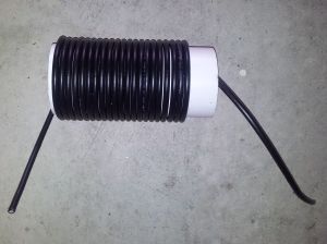
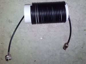
Here is what the ugly balun looks like after coiling and threading the coax:
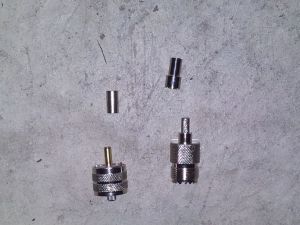
Next up was to put some connectors on the coax. I use UHF connectors for HF in the field (I also use it for 6m as well). I know that BNC is the QRP standard, but sometimes I’m QRO. I used a male UHF connector on one end to plug into the ATU, and a female connector at the other, for a run of coax to wherever I will operate the radio – keep in mind, this whole setup is for portable activations – typically Summits on the air (SOTA). These connectors I obtained at www.rfsupplier.com/.
UHF connectors need soldering of the inner conductor, but the shield is crimped. After doing this, the ugly balun is ready for use:
Testing
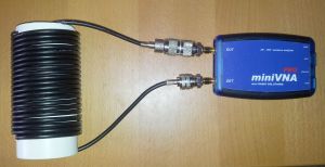
Now time for testing. The next activation is soon enough, and that will be the real test, but for now I wanted to see what was the insertion loss of this thing. I hooked up to a VNApro in transmission mode:
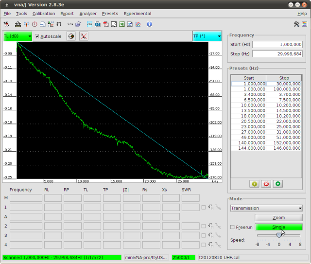
A screenshot of a test between 1 and 30MHz is shown below:
Essentially, the insertion loss is around 0.25db from 15m and up, which is close to coil resonance. Lower down, the insertion loss is lower, around 0.19db at 20m, 0.14db at 40m and lower loss on the lower bands. I am happy with this, it is not much higher than the pure loss of the coax itself. It is interesting that there are some loss factors aside from the losses to be expected from LMR195, hence the flat line around 21MHz to 30MHz, which would not happen on a simple coax run. It will be interesting to see how this goes in the field.
Regards,
Wayne VK3WAM
[…] tuner right on the feed point, with a tapped loading coil 1.6m above the feed point. The Ugly Balun which I have described here was also in attendance. This antenna is a little behind the end fed when the other station is in […]